
Introduction
A machine that fits inside a building may still be difficult to operate, maintain or connect efficiently. Bubble film line planning must treat extrusion, forming, cooling, lamination, winding, utilities, roll movement and downstream converting as one system. Because each product structure changes the required modules and working space, experienced bubble film machinery specialists such as ZTECH begin layout discussions with the finished product rather than a generic equipment footprint. This guide explains how to review an air bubble film machine layout before shipment, so installation does not reveal avoidable problems with access, material flow, maintenance or future expansion.
Quick Answer
First define the finished film, layer structure, working width, roll size and downstream process. Then obtain the final general arrangement drawing for the selected air bubble film machine and place each production stage in process order. Add space for operators, maintenance, component removal, raw materials, finished rolls and forklifts. Mark electrical, cooling-water and compressed-air connections, and check that the line does not block emergency routes. Finally, simulate material movement from resin storage to finished-product dispatch and reserve space and utility capacity for likely future modules.
Define the Product and Production Scope
Layout planning starts with what the factory intends to sell. A line for standard mother rolls does not need the same space as one that also laminates kraft paper, aluminum foil or EPE, or converts the film into perforated rolls, bags or mailers.
Confirm the Finished Bubble Film
Document the finished width, bubble size, layer structure, material formula, laminated material, maximum roll dimensions and final output form. Also confirm whether winding uses a core or a coreless system.
Layer count alone does not define the layout. A five-layer product made by inline lamination introduces unwinding, tension control and composite-roll handling that a basic two-layer line does not require.
Match the Machine Configuration to the Product
A bubble film making machine may include extrusion units, a die, bubble forming and cooling, lamination, edge trimming, winding and recycling. The selected process determines how many modules and feeding points are needed.
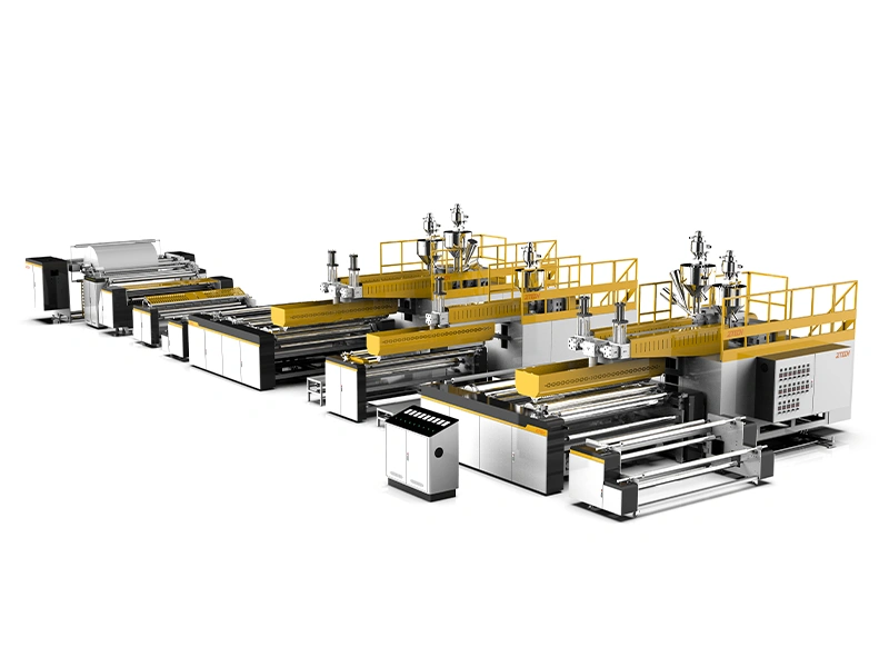
Within ZTECH's air bubble film machine range, two- and three-layer models support standard film structures, while five- and seven-layer systems can incorporate inline lamination for PE-coated facing materials. These additional modules increase the overall line length and require more space for unwinding access and composite-roll loading.
Define the Line Boundary
Decide whether the planned line ends at the main winder or also includes slitting, perforation, coreless rewinding, bag making, mailer production or scrap recycling. This prevents downstream equipment from being added later without operating and storage space.
Use Final Layout Data
A website image or quotation summary is not an installation drawing. The factory plan should use the general arrangement drawing for the final machine configuration.
Confirm the Complete Footprint
The drawing should show total length, maximum width and height, module positions, operator and service sides, control cabinets, material-entry direction, roll-discharge direction, safety doors and utility connections.
Do not copy dimensions from a similar model. A wider line, extra extruder, inline recycler, automatic winder or laminating unit can change both the footprint and working envelope.
Check Loads and Foundations
Ask the supplier to identify total weight, concentrated loads and any leveling, anchoring or foundation requirements. Confirm whether embedded parts, pits or special floor preparation are needed, then compare these requirements with the actual factory floor.
Arrange the Main Stages in Process Order
A practical layout follows a clear sequence:
Raw-material feeding → Extrusion → Bubble forming and cooling → Inline lamination when required → Winding
The objective is to keep materials, operators and finished rolls moving forward without repeated crossing or backtracking.
Keep Material Flow Consistent
Avoid layouts where resin passes through the finished-roll area, operators cross forklift routes, completed rolls return through raw-material storage, scrap crosses the main aisle or downstream equipment blocks access to the extrusion section.
Where the building forces a change of direction, verify roll-turning space instead of connecting machines tightly on paper.
Allow for Additional Modules
Extra extruders, feeding systems, recycling and automatic winding change the positions of hoppers, controls and service points. ZTECH five- and seven-layer inline lamination arrangements also need room for composite-roll loading, unwinding and access around the lamination section.
Plan Raw-Material Feeding and Storage
Place resin close to the correct feeding points and provide separate locations for virgin material, recycled material, additives, opened bags and materials assigned to different extruders.
A bubble wrap making machine with independently controlled layers may have several material routes. The layout should make it difficult to deliver the wrong formulation to the wrong hopper.
Manual feeding, vacuum conveying, mixing, drying and central supply all require different space and utility connections. Include the selected feeding equipment in the drawing, and check overhead pipes against ceiling height, lighting and maintenance access.
Calculate the Working Envelope
Machine footprint is only the area occupied by equipment. The working envelope also includes operators, open doors, maintenance, roll changes, lifting and component removal.
Add Operator Access
Provide practical access to controls, feeding points, the die, forming and lamination sections, the winder and inspection positions. Clearance should reflect the task being performed; a passage that permits walking may still be too narrow for cleaning, adjustment or roll loading.
Add Maintenance and Removal Space
The installation drawing should show where major parts are removed. Confirm enough space to open guards and cabinets, clean the die, inspect the forming roller, remove motors, rollers or screws and position a forklift or hoist.
A wall, column or downstream machine placed in the removal direction can turn routine maintenance into a major dismantling project.
Plan Finished-Roll Handling
The winding section often needs more space than expected because the roll must be unloaded, turned, inspected and moved away.
Confirm the Maximum Roll
Use the maximum specified width, diameter and weight, not the most common order. Confirm the unloading method and whether winding uses a core, shaft or coreless system. The largest roll must match the planned trolley, forklift or lifting equipment.
Simulate the Roll Route
Trace the roll from unloading through turning, transport, doors, inspection, temporary storage and any later slitting, perforation or bag-making process. Check the turning circle and doorway clearance with the actual handling equipment.
Create separate staging areas for rolls awaiting inspection, approved material, converting stock, rework and scrap. Otherwise, rolls tend to occupy service aisles or emergency routes.
Mark Utilities Before Installation
Utility planning should appear on the same drawing as the machine layout.
Electrical Supply
Confirm voltage, frequency, connected load, operating demand, cabinet position, cable route, grounding and spare capacity. Cable trays must not interfere with lifting or maintenance.
Cooling Water
Identify cooling equipment, supply and return points, pipe routes, drainage and leak control. Required temperature, pressure and flow must come from the final utility list, not from another model.
Other Services
Confirm whether the selected configuration needs compressed air, vacuum, process water, chilled water or exhaust. Keep hoses and pipes out of operator and forklift aisles.
Connect Downstream Equipment
Decide whether converting will be inline, adjacent or located in a separate area. Slitters, perforators, coreless rewinders and bag-making machines often have different speeds and changeover cycles from the extrusion line, so a roll buffer is useful even when the intended workflow is continuous.
Keep downstream categories clear in the plan. A slitter or bubble bag machine may be essential to the factory, but it is not part of the air bubble film machine unless included in the contracted configuration.
Check Safety and Future Expansion
Separate pedestrian paths, forklift routes, material storage and service areas where practical. Keep exits, fire equipment, electrical cabinets and safety doors unobstructed.
Do not use one universal aisle-width figure. Required clearances depend on local rules, handling equipment and the task performed.
Reserve space for likely additions such as automatic feeding, another extruder, inline lamination, automatic winding, inspection, slitting, bag making or recycling. Expansion planning must also include power, cooling water, compressed air, cable trays and material routes.
Final Factory Layout Checklist
Before approval, confirm that:
- Film width, bubble specification, layer structure and laminated materials are defined.
- Maximum roll size, unloading method and downstream scope are known.
- The final configuration list and general arrangement drawing match the order.
- Equipment dimensions, loads, service sides and removal directions are marked.
- Floor, foundation, clear height and equipment-entry routes are checked.
- Electrical, cooling-water and other utility connections are verified.
- Raw-material, finished-roll, scrap, forklift and pedestrian routes are workable.
- Operator access, maintenance space and emergency routes remain clear.
- Future modules and the required utility capacity have been reserved.
Conclusion
A successful layout is not proven by fitting a machine outline inside the factory. It is proven when the selected product can move through feeding, extrusion, forming, cooling, lamination, winding and converting without obstructing operation or maintenance. Start with the finished film, use the final equipment drawing, add the complete working envelope and simulate every material route. With those inputs defined, a line supplier such as ZTECH can prepare a configuration-specific installation plan instead of relying on a generic footprint.
FAQs
Should an Air Bubble Film Line Be Installed Against a Wall?
Not on a service side unless the maintenance drawing allows it. A wall may restrict cabinet opening, cleaning or removal of screws, rollers and motors.
How Should Ceiling Height Be Checked?
Allow for the tallest machine component, feeding equipment, pipes, cable trays, ventilation and any lifting needed for maintenance. Also verify that the largest module can enter through the factory door.
Does the Cooling System Need a Separate Room?
Not always. Its location depends on heat rejection, noise, pipe length, climate and access. Review it with the machine supplier and facility engineer.
Can Slitting or Bag Making Be Placed Directly After Winding?
It can be nearby, but direct transfer should not be assumed. Different speeds, changeovers, inspection and order schedules often require an intermediate roll buffer.
What Should Be Sent for a Supplier Layout Review?
Send a scaled factory drawing showing columns, doors, clear height, floor conditions, utilities, storage areas, forklift routes and exits, together with the target film and roll specifications.